Wafer Flow Control Valves
Wafer valve is the flow control valves are designed to fit between pipe flanges. They are available to suit a wide range of flange specifications, including British Standard, ANSI and numerous other specifications.
How do our Wafer Flow Control Valves work?
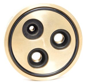
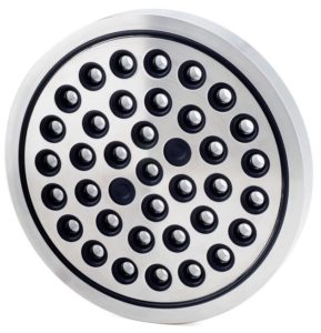
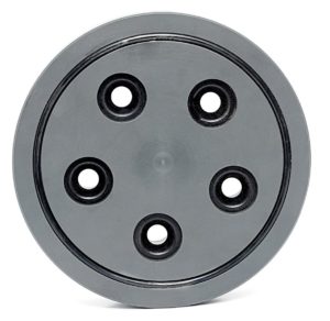
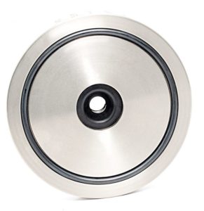
The Maric Flow Control Rubber is at the heart of the flow control valve, the diameter of the rubber orifice responds automatically to pressure fluctuations, adjusting to maintain a constant flow rate. As pressure differential increases, the orifice diameter reduces to maintain the pre-set flow rate. Likewise, as pressure reduces the orifice automatically opens up to maintain the pre-set, constant flow rate, regardless of pressure variations. As the rubber is constantly flexing within the valve body it is self-cleaning and does not clog.
Why choose Wafer Flow Control Valves?
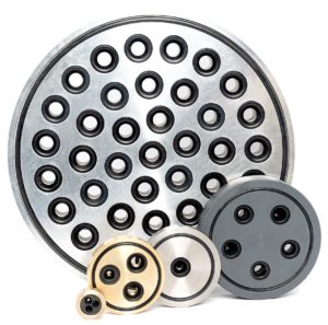
- Best choice for larger size valves, range goes from 3/4in (20mm) to 12in (300mm).
- Wide range of flow rates available from 5LPM to 8854LPM.
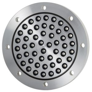
- Standard Wafer Valves orifice plate style are supplied and fitted with an O-ring on each side for sealing with the flange face. However full flange face wafer are available upon request and can be supplied with stub gaskets. See Photo 8.
- Easy to remove and refit by loosening all bolts and only remove one bolt completely to slip the wafer in and out.
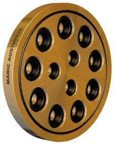
- Wafer available in Brass, U-PVC, Stainless Steel, Duplex, Bronze alloys or more unusual materials like Titanium and Inconel.
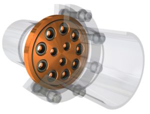
Positioning the Wafer Valve
Flange bolts will approximately locate the Wafer Valve concentrically in the pipe. There will be some clearance between the wafer OD and the bolts, this is normal, the Wafer Valve should be located as close as possible to concentric prior to final clamping.
Technical Data
Choose your valve body material and Control Rubber to fit your exact requirements
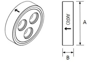
The dimensions shown in the table are representative of pipe flanges according to BS 4504 PN16 specification. Other flange specifications, such as BS10 and ANSI are also available.
Nominal pipe diametre | Nb of Orifi | Dimension A (mm) | Dimension B (mm) | Flow Rate Available LPM (Litres per Minute) |
|---|---|---|---|---|
3/4in. (20mm) | 1 | 61 | 22 | 0.2 / 0.25 / 0.3 / 0.35 / 0.4 / 0.5 / 0.63 / 0.7 / 0.8 / 1 / 1.1 / 1.2 / 1.3 / 1.5 / 1.8 / 2 / 2.3 / 2.5 / 2.8 / 3.2 / 3.5 / 4 / 4.5 / 5 / 6.3 / 7 / 8 / 9 / 10 / 11 / 12 / 13 / 15 / 16 / 18 / 20 / 23/ 25 / 28 / 32 / 36 / 41 / 45 / 49 / 54 / 59 / 66 / 73 / 82 / 91 / 102 / 114 |
1in. (25mm) | 1 | 71 | 22 | 0.2 / 0.25 / 0.3 / 0.35 / 0.4 / 0.5 / 0.63 / 0.7 / 0.8 / 1 / 1.1 / 1.2 / 1.3 / 1.5 / 1.8 / 2 / 2.3 / 2.5 / 2.8 / 3.2 / 3.5 / 4 / 4.5 / 5 / 6.3 / 7 / 8 / 9 / 10 / 11 / 12 / 13 / 15 / 16 / 18 / 20 / 23/ 25 / 28 / 32 / 36 / 41 / 45 / 49 / 54 / 59 / 66 / 73 / 82 / 91 / 102 / 114 / 125 / 138 / 150 / 162 / 180 / 199 / 216 / 233 / 256 |
1.1/4in. (32mm) | 1 | 75 | 22 | 0.2 / 0.25 / 0.3 / 0.35 / 0.4 / 0.5 / 0.63 / 0.7 / 0.8 / 1 / 1.1 / 1.2 / 1.3 / 1.5 / 1.8 / 2 / 2.3 / 2.5 / 2.8 / 3.2 / 3.5 / 4 / 4.5 / 5 / 6.3 / 7 / 8 / 9 / 10 / 11 / 12 / 13 / 15 / 16 / 18 / 20 / 23/ 25 / 28 / 32 / 36 / 41 / 45 / 49 / 54 / 59 / 66 / 73 / 82 / 91 / 102 / 114 / 125 / 138 / 150 / 162 / 180 / 199 / 216 / 233 / 256 |
1.1/2in. (40mm) | 1 | 86 | 22 | 0.2 / 0.25 / 0.3 / 0.35 / 0.4 / 0.5 / 0.63 / 0.7 / 0.8 / 1 / 1.1 / 1.2 / 1.3 / 1.5 / 1.8 / 2 / 2.3 / 2.5 / 2.8 / 3.2 / 3.5 / 4 / 4.5 / 5 / 6.3 / 7 / 8 / 9 / 10 / 11 / 12 / 13 / 15 / 16 / 18 / 20 / 23/ 25 / 28 / 32 / 36 / 41 / 45 / 49 / 54 / 59 / 66 / 73 / 82 / 91 / 102 / 114 / 125 / 138 / 150 / 162 / 180 / 199 / 216 / 233 / 256 |
2in. (50mm) | 1 | 98 | 22 | 0.2 / 0.25 / 0.3 / 0.35 / 0.4 / 0.5 / 0.63 / 0.7 / 0.8 / 1 / 1.1 / 1.2 / 1.3 / 1.5 / 1.8 / 2 / 2.3 / 2.5 / 2.8 / 3.2 / 3.5 / 4 / 4.5 / 5 / 6.3 / 7 / 8 / 9 / 10 / 11 / 12 / 13 / 15 / 16 / 18 / 20 / 23/ 25 / 28 / 32 / 36 / 41 / 45 / 49 / 54 / 59 / 66 / 73 / 82 / 91 / 102 / 114 / 125 / 138 / 150 / 162 / 180 / 199 / 216 / 233 / 256 |
2in. (50mm) | 3 | 98 | 22 | Maximum flow 342 |
2.1/2in. (65mm) | 4 | 111 | 22 | Maximum flow 456 |
3in. (80mm) | 3 | 130 | 22 | Maximum flow 699 |
4in. (100mm) | 6 | 162 | 22 | Maximum flow 1279 |
6in. (150mm) | 12 | 219 | 22 | Maximum flow 2320 |
8in. (200mm) | 19 | 276 | 22 | Maximum flow 4427 |
10in. (250mm) | 26 | 336 | 32 | Maximum flow 6058 |
12in. (300mm) | 38 | 386 | 32 | Maximum flow 8854 |
Tailoring solutions to your specifications
Akro Valve offer a wide range of flow control solutions, our technical experts will guide you through the process of selecting the right connection types, sizes, and materials. we can also modify our basic valve design to create equipment that meets your specific site requirements.
Pipes, valves and fittings for every project
Akro Valve offer a range of pipe fittings and tools for the repair and maintenance of water and fluids installations. We can supply pipes, fittings and tools to your requirements.